BXI Tool User Guide
1. Software Overview
Basic Information
- Name:
BXI_Tool - Icon:

- Version:
Latest - Languages: Chinese and English (switch in the top-right corner)
- Download: Go to Download Page
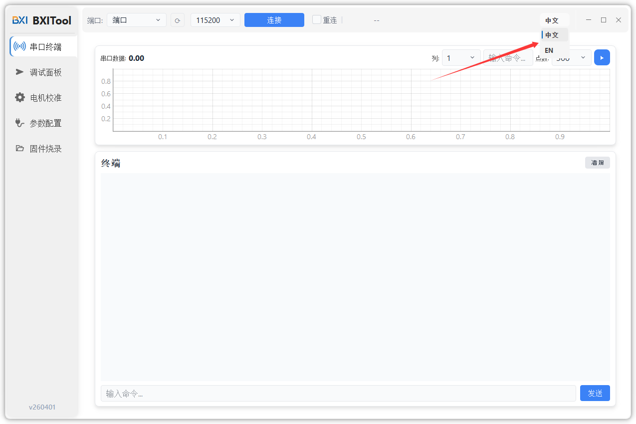
Interface Overview (Left Menu)
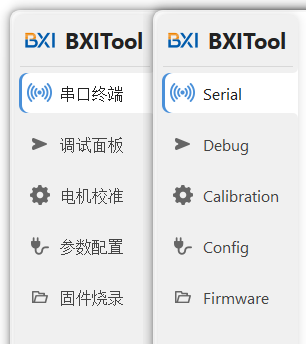
| Menu | Description |
|---|---|
| Serial | Quickly check motor output messages |
| Debug | Control the motor in MIT mode |
| Calibration | Complete magnetic encoder calibration |
| Config | Modify motor parameters |
| Firmware | Upgrade motor firmware |
2. Connect Motor via bxi_usb2can
2.1 Connect Serial Port
Use a USB-to-Type-C cable to connect the debugger to your computer:
- Type-C side to the debugger
- USB side to the computer
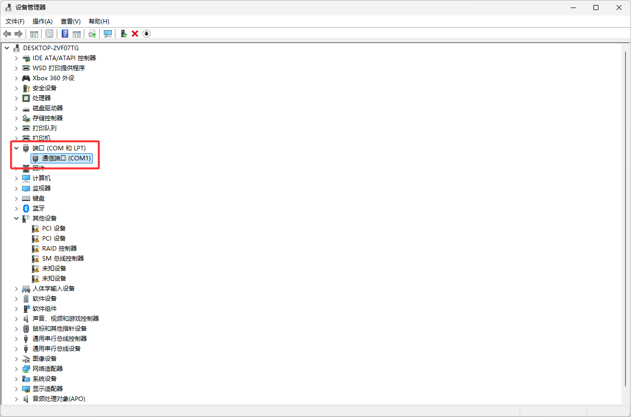
Find the correct COM port:
- Windows: right-click Start icon 鈫?Device Manager
- Expand "Ports (COM & LPT)"
- Find the COM port under "USB Serial Device" (e.g.
COM20,COM31)
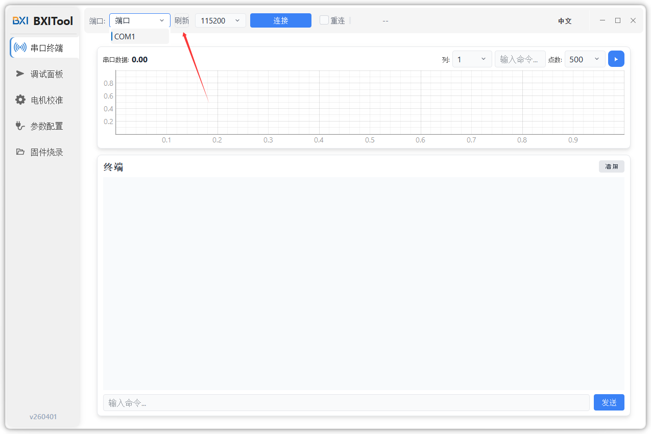
Open bxi_tool, then select the corresponding port from the top-left port dropdown. If no port appears, click refresh.
2.2 Select Target
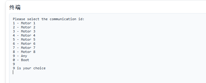
When the debugger is connected for the first time, it outputs a target selection menu:
- Input
1~8: communicate with the motor whosecan_idmatches that number - Input
9: receive output from all motors on the CAN bus, and use the latest receivedcan_idas output ID
Example: choose 9.
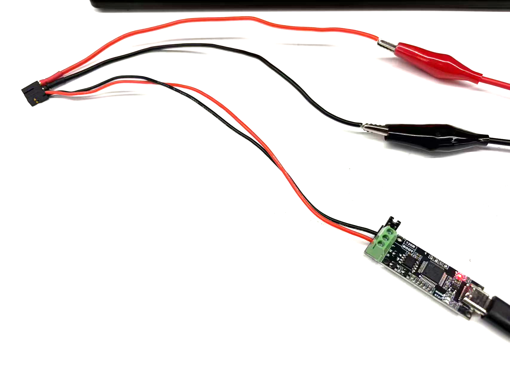
2.3 Connect Motor
Connect the motor and debugger through the 2+2 interface:
- Thicker wire: power line
- Thinner wire: signal line (red = H, black = L)
Recommended power input:
- Voltage:
24~48V - Current:
3~5A
After power-on, observe motor serial output.
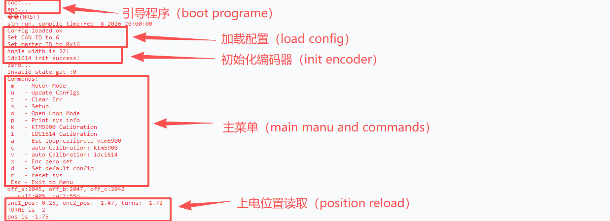
3. Serial Page
Used to view motor output and basic communication information.
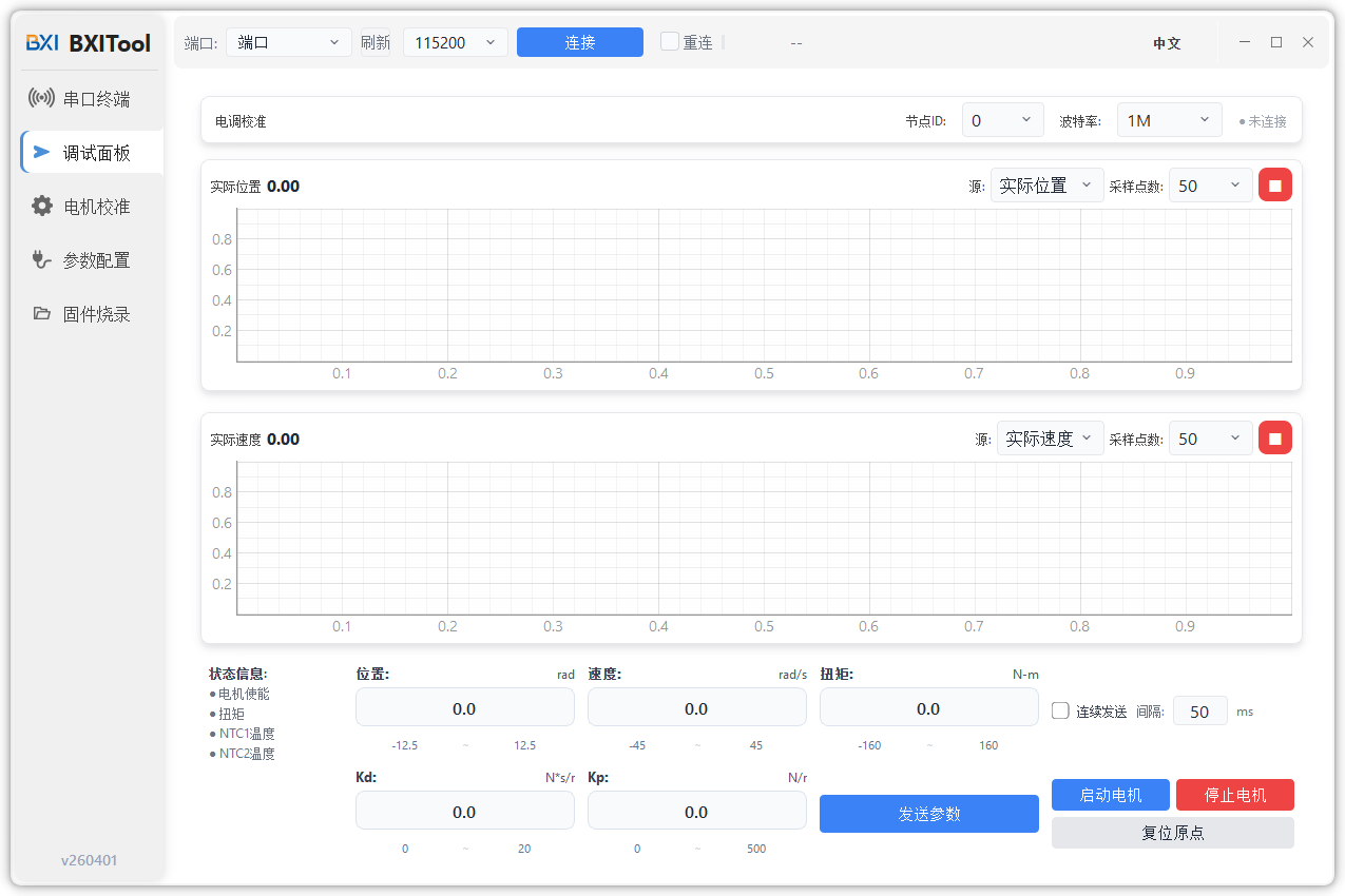
4. Debug Page
Used for MIT control debugging, command sending, and status monitoring.
5. Config Page
Used to modify motor parameters and communication settings.
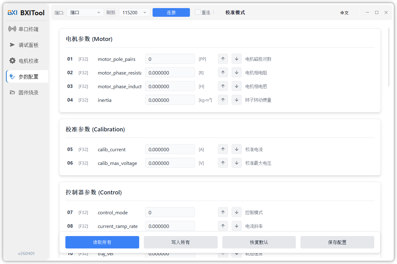
After connecting and powering on the motor, enter the left menu Config page to edit parameters.
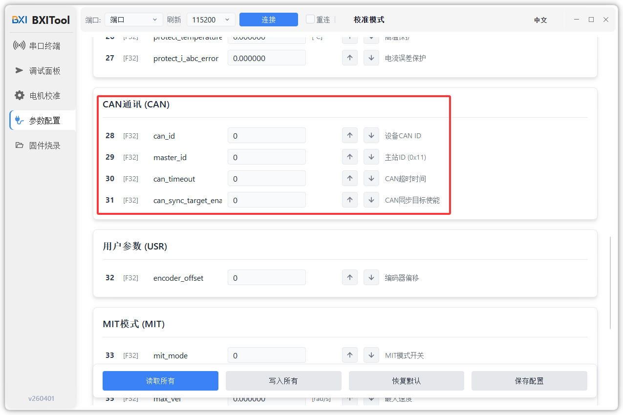
5.1 CAN BUS Settings
Scroll down to the CAN BUS section to modify CAN communication parameters.
Key parameters:
can_id: motor ID (the motor receives control frames sent to this ID)master_id: target sender ID (the motor sends feedback to this ID)
Common operations:
- Read ID: up arrow
- Write ID: down arrow
Rules:
- Writing
can_idwill also updatemaster_id = can_id | 0x010 master_idcan also be written independently- If you want to change only
can_idwhile keeping a specificmaster_id, writemaster_idagain after updatingcan_id
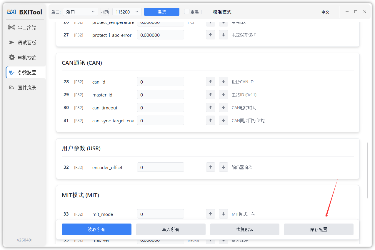
5.2 Save Parameters
To keep parameters after power-off, use the "Save Parameters" button at the bottom-right after modification.
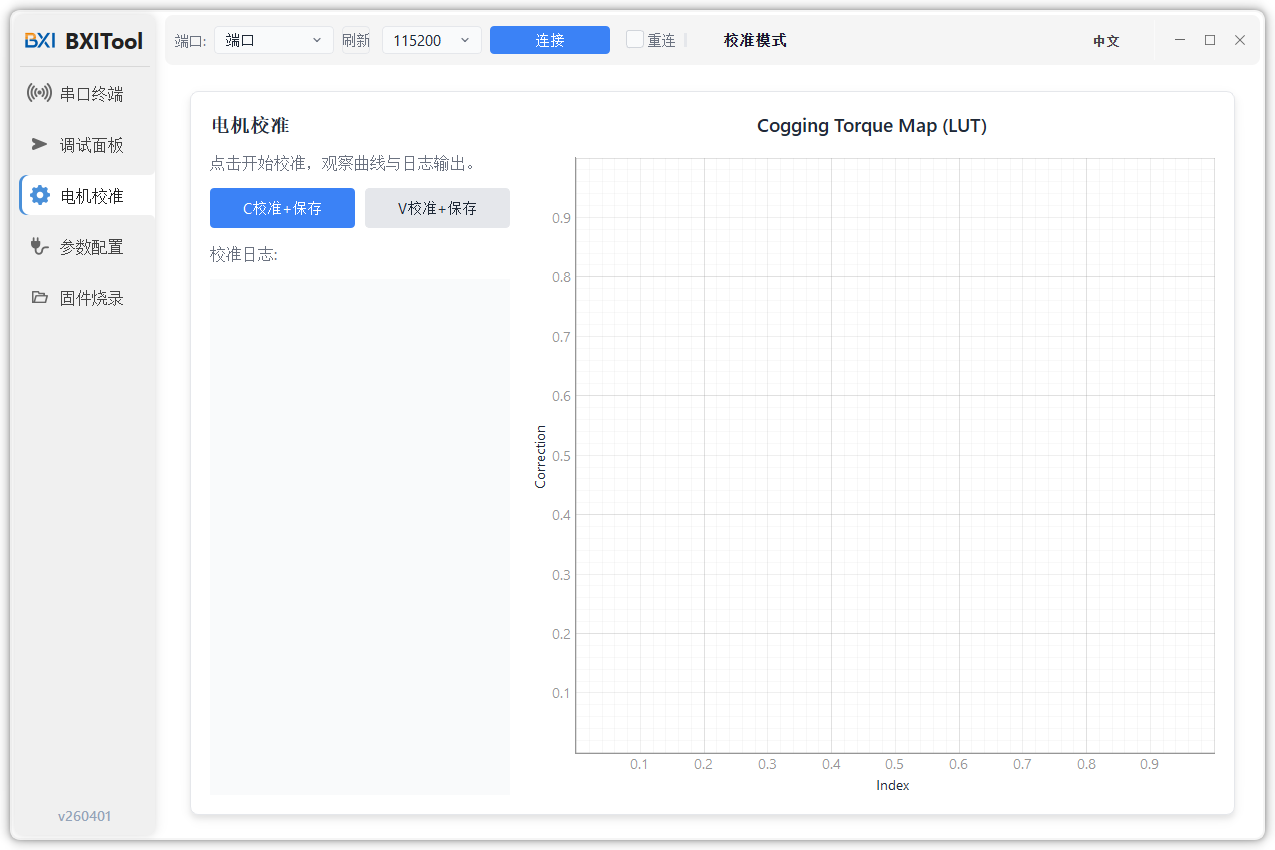
6. Calibration Page
Used to run the magnetic encoder calibration process.
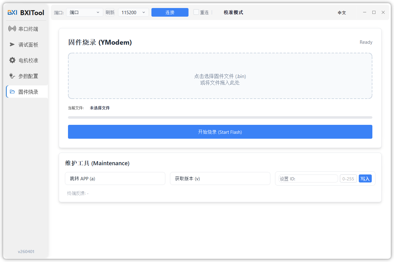
7. Firmware Page
Used to upgrade motor firmware.