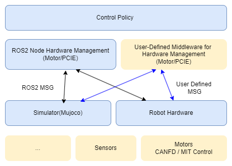
Control System Architecture
BXI provides a full-stack open architecture:
- CANFD-based motor hardware control and debugging interfaces
- MuJoCo-based simulation environments, robot URDF/XML resources, and related assets
- ROS2-based hardware management nodes, allowing control policies to be deployed seamlessly to simulation and real hardware
- Reinforcement-learning-based motion control training example code
CAN Bus & CAN ID
The robot has a total of 31 joint motors, distributed across 5 CANFD buses. Each bus corresponds to one body part:
| CAN Bus | Interface | Body Part | Motor Count |
|---|---|---|---|
| 0 | CANFD_0 | Waist & Neck | 5 |
| 1 | CANFD_1 | Left Leg (L_leg) | 6 |
| 2 | CANFD_2 | Right Leg (R_leg) | 6 |
| 3 | CANFD_3 | Left Arm (L_arm) | 7 |
| 4 | CANFD_4 | Right Arm (R_arm) | 7 |
The figure below is the URDF visualization of the robot, with each joint index annotated:
[Pending: insert the URDF visualization image with joint indices annotated here]
The table below lists the joint index, joint name, CAN bus, and CAN ID for every motor. Note that:
- The Joint Index is the index of the joint in the control program's joint/motor array, numbered continuously across the whole body starting from
0. - The CAN ID is the motor's address on its bus; it increments independently within each bus, starting from
1.
| Joint Index | Joint Name | CAN Bus | CAN ID |
|---|---|---|---|
| 0 | waist_y_joint | 0 | 1 |
| 1 | waist_x_joint | 0 | 2 |
| 2 | waist_z_joint | 0 | 3 |
| 3 | l_hip_y_joint | 1 | 1 |
| 4 | l_hip_x_joint | 1 | 2 |
| 5 | l_hip_z_joint | 1 | 3 |
| 6 | l_knee_y_joint | 1 | 4 |
| 7 | l_ankle_y_joint | 1 | 5 |
| 8 | l_ankle_x_joint | 1 | 6 |
| 9 | r_hip_y_joint | 2 | 1 |
| 10 | r_hip_x_joint | 2 | 2 |
| 11 | r_hip_z_joint | 2 | 3 |
| 12 | r_knee_y_joint | 2 | 4 |
| 13 | r_ankle_y_joint | 2 | 5 |
| 14 | r_ankle_x_joint | 2 | 6 |
| 15 | l_shoulder_y_joint | 3 | 1 |
| 16 | l_shoulder_x_joint | 3 | 2 |
| 17 | l_shoulder_z_joint | 3 | 3 |
| 18 | l_elbow_y_joint | 3 | 4 |
| 19 | l_wrist_x_joint | 3 | 5 |
| 20 | l_wrist_y_joint | 3 | 6 |
| 21 | l_wrist_z_joint | 3 | 7 |
| 22 | r_shoulder_y_joint | 4 | 1 |
| 23 | r_shoulder_x_joint | 4 | 2 |
| 24 | r_shoulder_z_joint | 4 | 3 |
| 25 | r_elbow_y_joint | 4 | 4 |
| 26 | r_wrist_x_joint | 4 | 5 |
| 27 | r_wrist_y_joint | 4 | 6 |
| 28 | r_wrist_z_joint | 4 | 7 |
| 29 | neck_z_joint | 0 | 4 |
| 30 | neck_y_joint | 0 | 5 |
Domain ID
Purpose
The robot control system is built on ROS2, which uses DDS for inter-node communication at its core. ROS_DOMAIN_ID partitions the communication domain:
- Nodes with the same Domain ID can discover each other and exchange topics/services.
- Nodes with different Domain IDs are isolated from each other and do not interfere.
When multiple robots exist on the same local network, or multiple debugging hosts are connected at once, using the same Domain ID causes topic data to cross-talk and leads to abnormal control behavior. Assigning each robot a unique Domain ID isolates each robot's ROS2 communication network from the others.
Default Domain ID
Each robot is configured with a default Domain ID at the factory according to the following rules. The value depends on how the robot is started:
- Gamepad startup:
ROS_DOMAIN_ID = generation × 10 + robot serial number. ELF3 is a third-generation product, so the generation number is3, and the Domain ID is30 + serial number.- Example:
elf3-15→3 × 10 + 15 = 45 - Example:
elf3-20→3 × 10 + 20 = 50
- Example:
- APP startup:
ROS_DOMAIN_IDis fixed at22.
How to Configure
The Domain ID is set via an environment variable. Run the following in a terminal on the robot host or development host:
export ROS_DOMAIN_ID=45
To apply it automatically on every boot, add the command to ~/.bashrc:
echo "export ROS_DOMAIN_ID=45" >> ~/.bashrc
source ~/.bashrc
Notes
- The recommended range for
ROS_DOMAIN_IDis0–101. - The host (development machine) must be set to the same Domain ID as the target robot in order to communicate with it.
- Restart the relevant ROS2 nodes after changing the value for it to take effect.
Documentation Directory
- ROS2-based control policy deployment framework with seamless deployment to simulation and real hardware: https://github.com/bxirobotics/bxi_rl_controller_ros2_example
- Robot URDF resources: https://github.com/bxirobotics/bxi_rl_controller_ros2_example/tree/main/resources